Project idea
Microphone array that allows for beamforming.
Requirements
- 4-6 microphones
- Analog filtering
- Analog to digital conversion for on-computer digital filtering
Part Selection
Microphones
Requirements
- Must meet $20Hz - 20kHz$ voice-band frequency range
- Must allow for analog sampling
- Preferably a MEMs microphone
- Since it’s cheaper
- And usually smaller
- Must have datasheets and models because I don’t hate myself
Part selection:
https://www.digikey.com/en/products/detail/tdk-invensense/ICS-40618/6025653
Application notes
From the datasheet 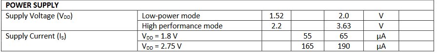 we can see the microphone array datasheet input requirements.
Since we’ll always want to operate in high performance mode, we can pick $3.3V$ for a power supply target voltage. This means that the power supply will need at a minimum to be able to support $0.2mA$ per microphone.
The datasheet also points to some relevant application notes.
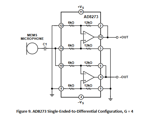
AN-1140 – Microphone Array Beamforming AN-1165 – Op Amps for MEMS Microphone Preamp Circuits
The pre-amp circuit specified in the datasheet is
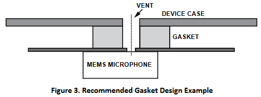
AN-1003 – Recommendations for Mounting and Connecting InvenSense MEMS Microphones
Datasheet suggests avoiding acoustic resonances from a Helmholtz resonator. However, we will just not bother with that and leave the microphones exposed for now. I really don’t want to get into the nitty-gritty of mechanical design. 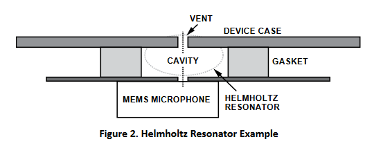
Now we can select an appropriate ADC since these microphones are essentially fine…
ADC
Requirements
- Must meet $20Hz - 20kHz$ voice-band frequency range
- Must have datasheets and models because I don’t hate myself
Part selection:
https://www.digikey.com/en/products/detail/cirrus-logic-inc/CS5366-CQZ/923209
Application Notes
From the datasheet we see that the recommended input buffer looks like:
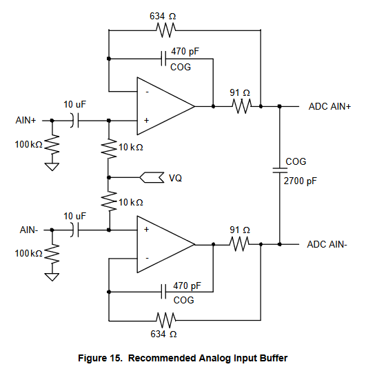
This pre-amp stage is used in the final design.
From the datasheet we also see that the recommended typical connection diagram is the following:
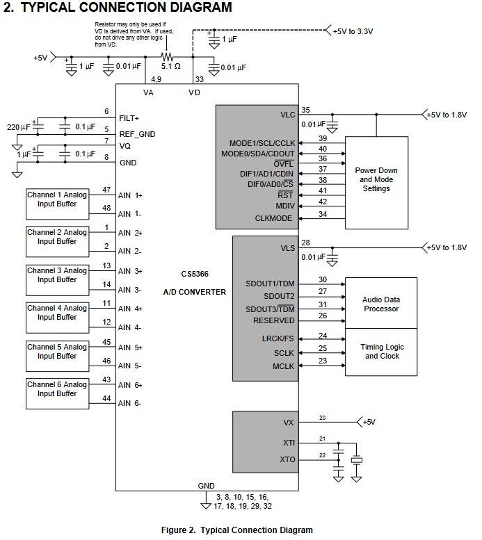
This means that we require a crystal oscillator that oscillates at a frequency between 1 and 6 $MHz$. I picked something out of the sky at $4MHz$.
https://www.digikey.ca/en/products/detail/ecs-inc/ECS-40-20-5PXDN-TR/827400
After trying to read the datasheet for a few hours I have discovered I’d rather not use this one for arbitrary reasons and not just because I couldn’t figure it out.
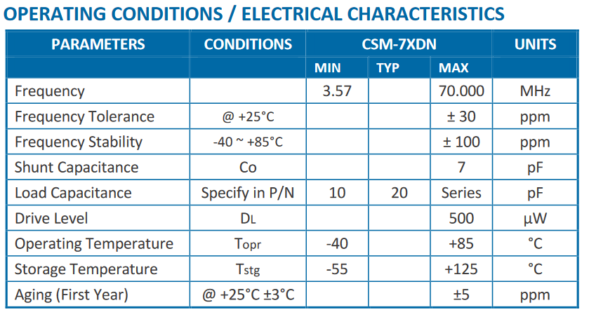
I am instead going to use this one. It’s much simpler for simple people like me.
We can see that the typical usage is very simple:
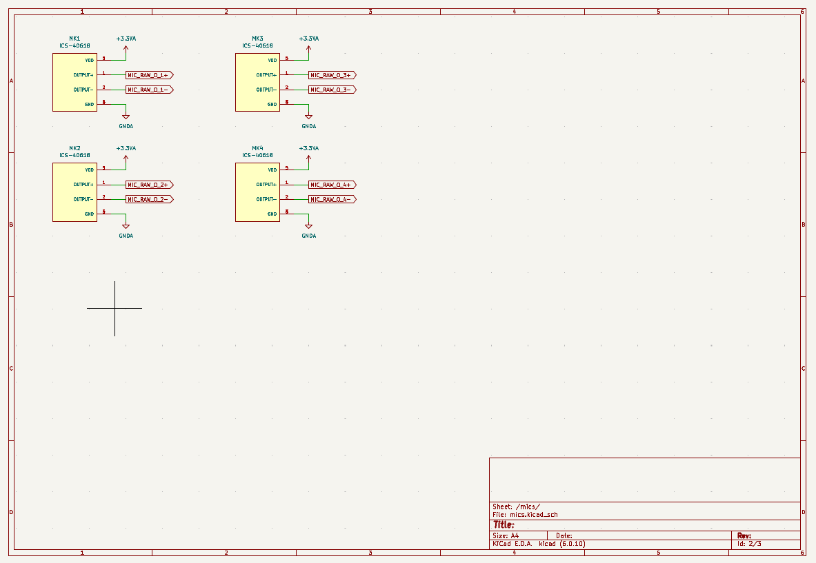
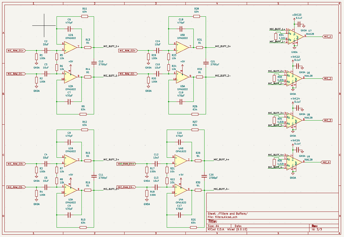
Schematic
To do the schematic we first need to break out the microphones.
We then need to pre-amp the microphones and use an instrumentation amplifier to retrieve the differential mode signal.
The instrumentation amplifier resistor was selected to provide a gain of $50x$
The datasheet is here for the INA128
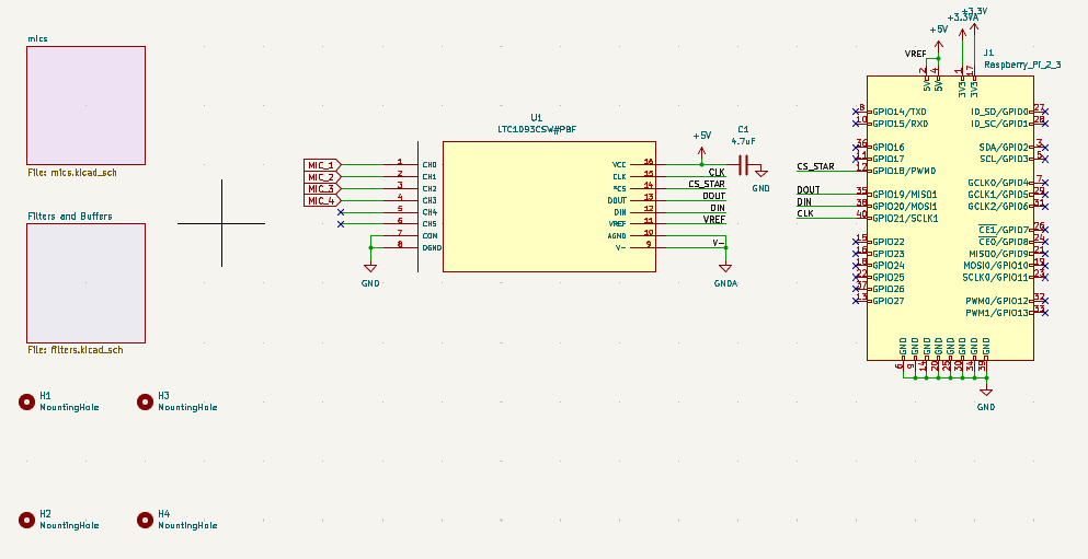
And now the ADC to raspberry breakout schematic looks as follows:
Layout
Since we want to be able to do beamforming, we can place them along some sort of array pattern, a square with side lengths of $100mm$ is a good start.
We can put the rats-nest down.
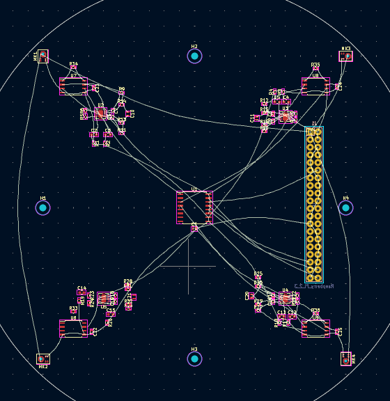
The R-Pi breakout is placed on the opposite side to minimize interference of the Pi with the mics.
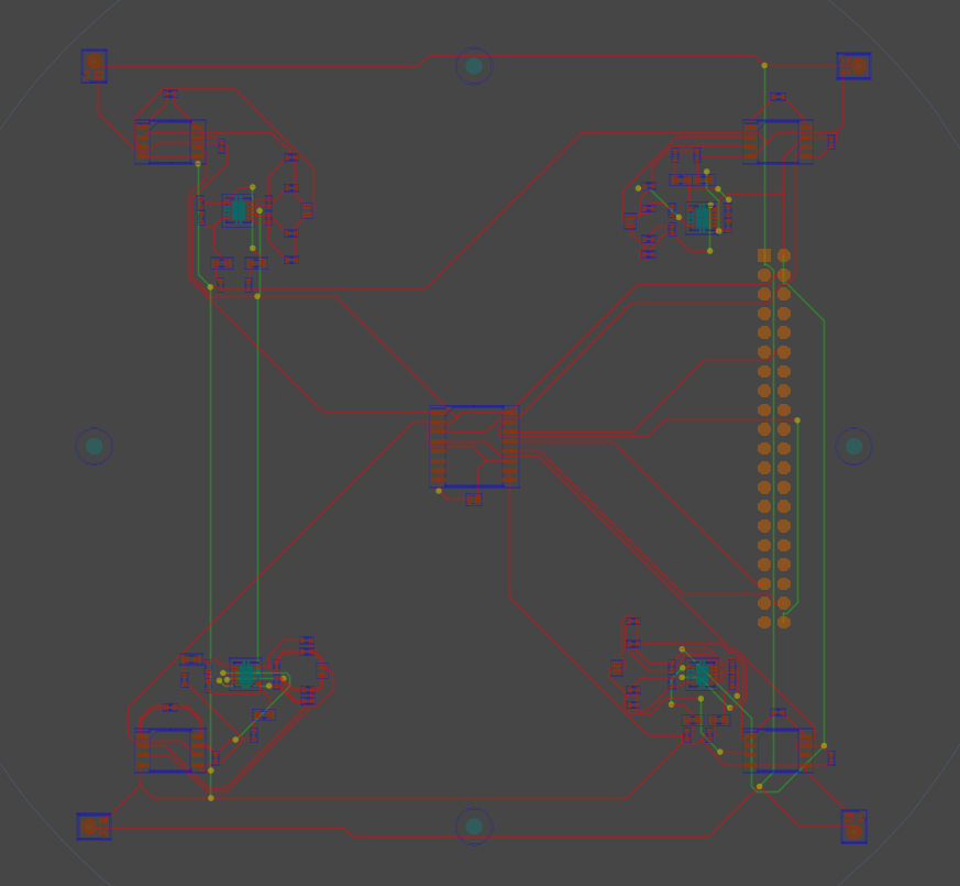
Routing
Routing is done starting with the local areas, I place components as well as I can. I’m sure this could’ve been done better, but I’m not super experienced with this.
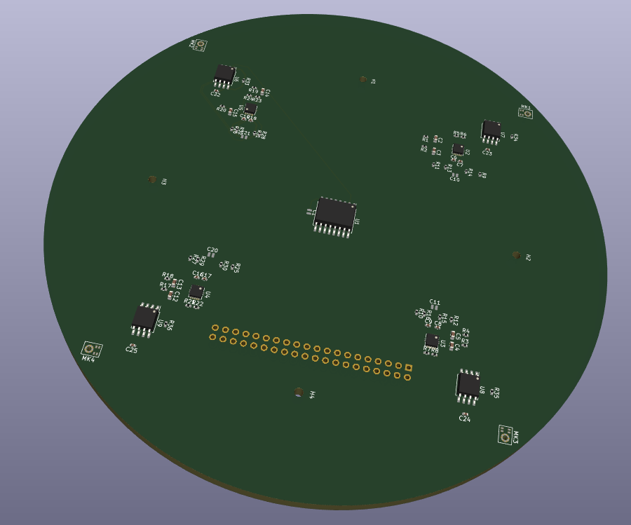
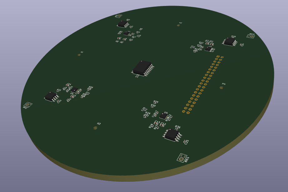
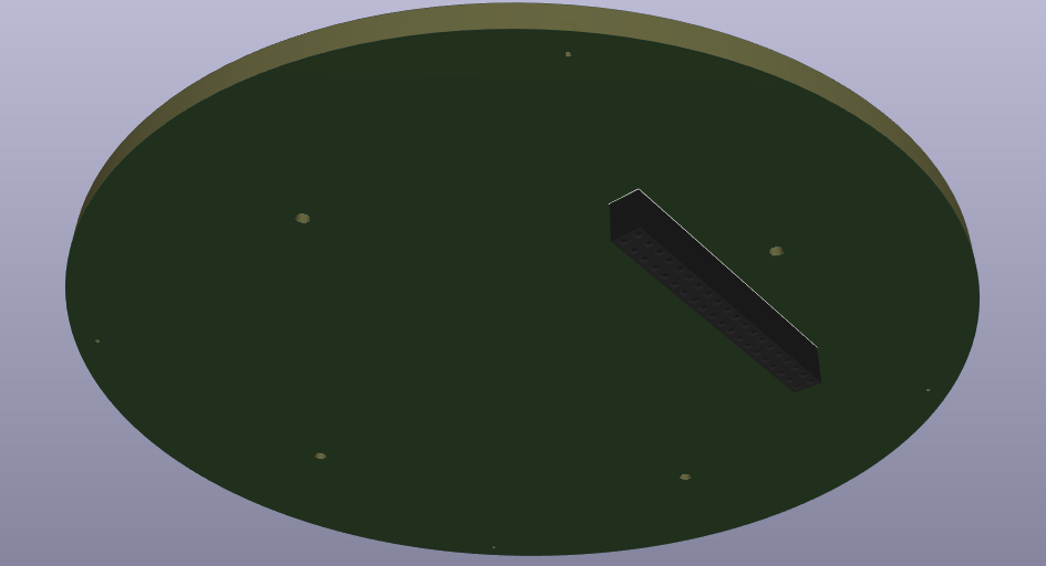
3D model
And now the final model looks like.